FAQs.
-

Technical & Installation -

Controls -
Product -

Packing & Transport -

General - Speak to the team today
Contact us
Technical & Installation
In the event of a low, or no airflow the TCO will operate to switch off the electrical supply to the heating elements on electrical heated units. This prevents a dangerous situation where overheating electrical elements could start a fire.
The most common reasons for the TCO (or both TCO’s in the case of 2m units) tripping are incorrect installation, insufficient maintenance, or inappropriate heat and fan settings.
Incorrect installation
- Make sure surface mounted units are not fitted in the ceiling void.
- Check the gap above the air curtain. For surface mounted units this should be at least 100mm.
- Make sure the discharge air stream is not being deflected back into the cabinet by the top edge of the doorway or any other doorway obstruction.
Insufficient maintenance
- Check air ventilation holes and inlet/outlet grilles are not blocked
- Make sure the fan impellers, housing, motors and filters (if fitted) are free of dust and debris
- Ensure the whole unit is thoroughly cleaned at least every three months. See O&M instructions for details
Inappropriate heat and fan settings
- Check the controller settings are correct for the situation and conditions e.g. within small lobbies.
- Air curtain should always be switched on, and off, from the remote control to allow the run-on cycle to function
- When air curtains are in operation, and the mains supply is isolated, the run-on cycle cannot function.
- The last-man-out switch (if fitted) should always be operated turning the unit off with the Control unit and the fan run-off cycle has finished.
On surface mounted and recessed units, the TCO is labelled ‘Press to reset’. On Designer units, it is marked with a red circle.
Surface mounted units
On C and PHV units the TCO is located on the top of the outer case. On T Units it is inside the fan deck, and the grille needs to be removed to access it.Recessed units
On all recessed air curtains, the TCO is located inside the unit above the electric elements. The grille core will need to be removed in order to access the TCO.Designer units
On Designer units, the TCO is around ten holes in from the left and three rows in from the back and is behind a bigger air hole.Air curtains manufactured from 2015 onwards:
The LEDs on the Touch remote control will flash on and off.
Air curtains manufactured before 2015:
The status LED on the Touch PCB inside the air curtain will be continuous red. (You will need to access to the air curtain to check this).
Before resetting ensure there is adequate air flow from the air curtain, and that the unit has been commissioned as per the installation, operation and maintenance instructions.
Air curtains manufactured from 2015 onwards:
Click here to view our how-to guide on how to reset your overheated Air Curtain: How to reset your air curtain
Switch off the electrical supply to the air curtain and allow 10 minutes for it to cool down. Then turn the power back on and press the Auto Reset button on the Touch remote control four times.
Air curtains manufactured before 2015:
Switch off the electrical supply to the air curtain and allow 10 minutes for it to cool down. Access the TCO inside the unit and press the red button until it clicks in (There are two TCOs on 2m units or longer; you may need to reset both). Switch electrical supply back on.
Air curtains manufactured from 2015 onwards:
The air curtain heaters will come back on and, after 30 seconds, the LEDs on the remote control will stop flashing.
Air curtains manufactured before 2015:
The air curtain heaters will come back on and the status LED on the Touch PCB inside the air curtain will change from continuous red to flashing green.
Check that no wires are trapped, and all connections are correct. Make sure all fuses have the right breaking capacity (maximum current that can be safely interrupted by the fuse). See the O&M instructions for more details?
The internal fuses are located on the Touch PCB and inside the air curtain:
- Fuse 6.3A(T) supplies the fan motors within the air curtain
- Fuse 100mA(F) controls the circuitry of the Touch PCB
Joining kits are available for C, T, HP, HX, and PHV surface mounted air curtains. For more information call our Sales Office on 02476 384 646
- Check all wires are correctly connected to the control panel, elements and wall controller.
- For electric models ensure the correct supply is present and appropriately connected. Most electrical heated models require a 3-phase 400v electrical supply, they will not heat with a 1-phase 230v supply.
- The Thermal Cut Out (TCO) may have tripped and overheated
Under normal operating conditions the casing temperature should be between 60-80°C. A thermal protection device is embedded in the winding of each motor to prevent overheating.
The most likely cause of the motor running hot is a build-up of dust or dirt deposits on the fan impellers. This can cause vibration, noise and excessive wear on the motor bearings.
Regular cleaning will minimise the risk of overheating, optimise the efficiency of your air curtain, and prolong its operating life. We recommend that units are cleaned at least once every three months.
Some electric units can be downrated in the factory before the units are despatched at no extra cost. Contact Thermoscreens sales office for more information.
Please note that 1 phase units may well not provide enough heat output for a normal air curtain installation.
No. We do not recommend downrating units on site. Any conversion needs to be carried out at the factory at the time of order, or by a recognised Thermoscreens technician. Converting a unit yourself will invalidate your warranty.
Single phase units have a bridge on the terminal block, which connects L1, L2, L3 together. With three phase units, there is no bridge.
Unfortunately, we cannot down rate water heated units. However, you can manually reduce the output by selecting half heat on the controller. This will half open the three way valve. Please note that this may well not provide enough heat output for a normal air curtain installation.
Yes, all you need to do is purchase a 3m interconnecting cable. Change the position of DIP switch three on the master unit to ON and turn the DIP switch on the slave units to the OFF position. Refer to the installation, operation and maintenance instructions for more details.
A single Touch controller can operate up to eight units.
All DIP switches are pre-set for normal operation (with the exception of Designer and vertical units). It is only necessary to change the DIP switch settings if the air curtain is to be operated on a master/slave basis.
To provide a coil calculation, we need the following details:
- Air curtain type and size
- Water temperature in
- Water temperature out
- Room temperature
The difference in heat may vary even with small differences in water and air temp. Standard room temperature in our calculations is 20 C.
Please note we calculate for the air curtain operating at high fan speed.
When an air curtain is turned off for an extended period of time, dust and debris can settle on the electric heating elements. Before switching any unit back on it should always be inspected and cleaned to ensure safe and efficient operation.
If you are in any doubt, please contact the Thermoscreens service department.
Heating problems are usually associated with the connection to the controller or by insufficient water flow.
- Verify the status of the LED on the Touch PCB board
- If the LED is flashing green: operation is normal
- If the LED is flashing red: this means low supply voltage, remote control not plugged in or RJ cable fault
- If the LED is permanently on red: this means overheat safety cut-out(s) open circuit from an overheat situation
To reset a overheat safety cut-out:
- Switch off the electrical supply to the air curtain
- Allow time for the air curtain to cool down, typically 10 minutes
- Switch on the electrical supply to the air curtain
- Press the Auto button on the Touch remote control 4 times
Air curtain heaters will then operate and after 30 seconds the LEDs on the remote control will stop flashing and the status LED on the Touch PCB in the air curtain will flash green.
- Check the diverter valve is wired correctly to the PCB board. See wiring diagram in the instructions.
- Make sure there is no air in the heating coil or system, and bleed the unit if necessary
- Check the hot flow and cold return to ensure there is a sufficient water flow rate
If the water flow is low, the system may need balancing, or the pump may be faulty or too small.
Check the connections to ensure there is no loose wiring. Make sure the fan is correctly aligned and not binding on anything. Check the elements, contractor and PCB board for faults. Then recheck both two motors, if one of them has seized it will need to be replaced.
It is very important to connect ports A and B correctly. A to the water coil and B as the bypass. See figure below showing heating pipe work.
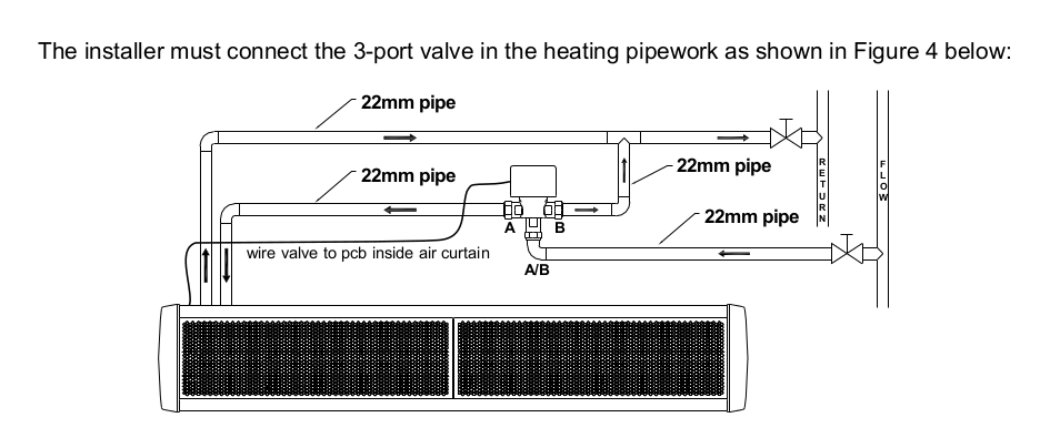
If the unit is fitted without the three-way valve the fan settings will work correctly, but you will not able to change the heat settings on the unit in automatic or manual mode. The only way to control the heat output without the three-way valve is using the valves built into the water system.
Controls
The status LED is fitted on the PCB board inside the air curtain and shown as LED1 on the wiring diagrams.
A pulsing green light means the unit is operating correctly.
A pulsing red light indicates a low supply voltage, or that the Touch controller is not connected to the unit. Check the wiring between the PCB and controller.
If the LED alternates between green and red the DIP switches are incorrectly set (refer to Operators Manual for details).
A permanent red light on an electric unit means the Thermal Cut Out has tripped and needs to be reset.
On the LPHW unit a permanent Red light indicates that a connector is missing and there is an open circuit. Both pins on the J2 location on the motherboard must be connected to close the circuit.
EcoPower PCB (V6) and earlier are fitted with a four-way screw terminal plug and socket system. To fit a new controller (T7263630) you will need to purchase a new PCB (V8) mother board (T7263601).
Our PCB has been updated several times in recent years as outlined below:
PCB v10 (September 2022 – today) – V10-E and V10-W versions added
PCB V9 (2013 – Sept 22) – IN0 and IN1 functions
PCB V8 (March 2008 – 2013) – RJ plug, inhibit connection
PCB V7 (June 2006 – March 2008) – RJ plug, NO inhibit connection
PCB V6 (and earlier) – 4 way socket, NO inhibit connectionDoor limit switches can be fitted to all units using IN1 on PCB version 9. However, we recommend door switches are only used with ambient models. Electric and LPHW units take time to heat up. If the door is opened and closed quickly, the heat from the element/coil will not have sufficient time to reach full capacity.
The controllers standard 6m cable can be extended up to 50m. The extended cable must be routed away from electrical and data cables to avoid noise and impaired functionality.
The controller should be connected to the air curtain and control functions tested before the cable is extended. Ensure each of the four wires (0V, Data, 0V and 12V) is connected correctly. We recommend that you use the Thermoscreens RJ coupler T5951030 when commissioning.
Product
Time clocks can be fitted to existing units. We recommend the Horstmann Centaur Plus C17 Series 2 or equivalent, 7-day single channel time switch with volt free contacts. Part number: T7851035. Refer to instructions for the correct wiring installation.
All of our products are fitted with a data plate, which shows the serial number and model type.
Surface mounted units: The data plate is located behind the left hand end cap.
Recessed units: The data plate is located inside the unit on the left hand side of the casing.
NB: left hand refers to when the unit is hanging in situ above the door
Standard parts vary for different fan decks:
T, HP, HX and PHV units are supplied with motor and impellors.
C Series ambient units are supplied with motor and impellors.
C Series electric units are supplied with motor, impellors and elements.
Filters are fitted as standard on T & HP surface mounted air curtains and all HP DX, PHV and DX units.
Packing & Transport
The Touch controller and wall brackets are both packed inside the unit. The controller is wrapped in bubble wrap and wall brackets are boxed to avoid scratching the casing.
LPHW units are supplied with a three-way valve as standard:
Units up to 2m long – are supplied as one unit with one valve packed in a separate box.
Units 2.5m and 3m long – are supplied as two units with a valve packed in a separate box within each unit
General
The Amps per phase for a unit is calculated based on Watts / 230 + 2 Amps for each motor.
Single phase:
E.G 6kw 1m unit 6000 /230=26.08 + 2 Amps (fan motor) = 28.08 round up to 30 Amps
E.G 6Kw 2m unit 6000 /230=26.08 + 4 Amps (2 fan motors) = 30.08 round up to 30 Amps
E.G 9Kw 1m unit 9000 /230=39.1 + (2 Amps for the fan) = 41.1 round up to 42 Amps
E.G 9Kw 2m unit 9000 /230=39.1 + (4 Amps for the fans) = 43.1 round up to 44 Amps3 phase:
For 3 phase calculations divide the answer by 3 to achieve the Amps required.
The fitting of BMS on/off varies depending on PCB being used:
Ecopower PCB version 9 – there are many different control features – see installation, operation and maintenance instructions.
Ecopower PCB version 8 (with INHIBIT) – remove the link and plug in the cables (volt free switch)
Ecopower PCB version 7 or less – identify data cable from the controller (usually the red wire), cut it and fit a volt free switch.
Testimonials
“We’ve been very pleased with your products and would like to continue using them as a design feature in all our shops.”
- Project Manager, large ice-cream manufacturer.
“Wrapped up and gone before the lunch service, great turnaround from order to delivery.”
- Director, Restaurant in Aldwych
“Thank you for having an excellent working relationship with me, you are a credit to Thermoscreens.”
- Technical Engineer, HVAC
“The new air curtains in the freezer room have completely eliminated any ice and frost build up around the room, including the evaporators. As the main reason for cold room failure, this will undoubtedly help to reduce costly downtime, stock loss and maintenance calls.”
- Refrigeration Manager at leading supermarket
“The units we installed at Birmingham this week. We really enjoyed installing your units and would like to use them moving forward with the other stores.”
- Installer, Restaurant in Birmingham
“I would like to take this opportunity to thank you all for your performance, we have all been very impressed with your response to queries and turnaround of air curtains.”
- Installer, HVAC
“Thank you for all your support. We couldn’t have won this project without your assistance.”
- Senior engineer